Lesson 2: Signal Flow
Signal flow may be one of the most broad topics of audio; it encompasses multiple facets of the audio world and is also incredibly important to day-to-day engineering work-flow. Stretching from electronic voltage considerations to inner workings of an analog or virtual console, this is the knowledge that becomes the technical foundation upon which every audio engineer bases his or her entire understanding.
Standard Audio Levels
For starters, every recorded audio signal goes through a few different stages before it reaches the speakers or headphones before reaching our ears. Each one of these stages has its own approximate and measurable voltage level, and a reference for that level. A reference is a standardized average measurement for what a signal’s estimated voltage will be. Still confusing? Let’s dig a little deeper.
The most common audio voltage levels are as follows:
Microphone Level = -58 dBu to +2.2 dBu = 1 millivolt to 1 volt
Instrument Level = -17.7 dBu to +7 dBu = .1 volt to 1.736 volts
Line Level = -4.8 dBu to +4 dBu = .447 volts to 1.228 volts
Speaker Level = +7 dBu to +30 dBu and above = 1.736 volts to 24.5+ volts
While the values for these levels can vary and overlap quite a bit, the average levels (references) are around here:
Mic Level = -30 dBu = 24 mV
Instrument Level = 0 dBu = .775 V
Line Level = +4 dBu = 1.228 V
Speaker Level = +14.26 dBu = 4 V
While you may not need to know these numbers offhand, it's mostly important to recognize which one of these levels is present when working with any particular source. For example, when using a microphone, acoustical energy is the input, while mic level is the output. When working with a mic preamp, mic level should be at the input, and line level at the output. When using a power amplifier, line level should be at the input and speaker level should be at the out. Instrument level outputs include guitar and bass pickups, as well as the 1/4” output of acoustic guitars and other acoustic instrument pickups.
In practice, these different levels are important in optimizing signal to noise ratio, preventing distortion, and achieving the best possible sound quality. For starters, all recorded signals are generally recorded at line level. This is also the voltage where the most signal processing happens, i.e. EQ, compression, reverb & delay. Another point to remember is that microphones output mic level, and that they require a mic preamplifier to raise that level to the recordable line level audio. Here are some rules to help you remember what goes where:
- Microphones need mic preamps directly after them.
- Line or speaker level signal should NOT be sent into a mic preamp.
- Signal must be at line level to be recorded.
- Instrument level signal needs a DI (direct injection) box to be recorded properly.
- Speaker level signal is very high voltage signal, and should ONLY be fed to speakers.
Audio Levels in Practice
Anytime a recording session is happening, the engineer is organizing all of his/her signal flow routing in a way that makes sense technically and aesthetically. The aesthetics will come with experience, but the technical practice comes with knowledge. Accomplishing this on a technical level can be rather simple, but staying organized is the key to session zen. Track counts and names can be overwhelming to memorize; as there are more and more of them, writing this information down will give you the chance to focus on the big picture: the music. Here’s a basic rundown of the usual signal flow in a recording studio:
Microphone >> Mic Preamp/Console Channel >> Analog to Digital Converter >> Multitrack recorder (computer) >> Digital to Analog Converter >> Monitor Input on Console >> Console Mix >> Speaker Amplifier >> Speakers
In every studio, the actual signal flow will change slightly, but the basic concept of this simplified signal flow chart still remains the same. The challenge lies in finding out how to get from one stage to the next. In some studios, it may be much easier than others. Luckily, in most professional studios, someone thought of this before building the space and tried to make it as simple as possible. Let’s focus on the common thread that all studios need to organize their signal flow: cables.
Cables, Connectors, and Connection Types
Cables are everywhere in a recording studio. They are what makes signal flow and, in turn, recording possible. There are enough types to make your head spin. For the most part, each cable & connector combo has a job it is most commonly used for. There’s also two main categories, analog cables and digital cables. In this lesson, we’ll take a look at analog cables.
Analog cables come in two main flavors, balanced and unbalanced. Both of these types of cables have a total of three signal carriers (aka “leads”) inside the cable. The difference is that in a balanced connector, all three of the signal carriers remain electronically independent. Those carriers are the positive signal, the negative/neutral signal, and the ground/earth signal. With an unbalanced connection, the neutral signal and the ground signal are electrically tied together. Both of these cables have their strengths and weaknesses.
Balanced Cables
These types of cables are the most common in recording studios. The three separate leads create a low noise cable that helps reject interference. Audio signal in a balance cable is carried on the “hot” and “cold” leads, while the ground signal is carried in a tin sleeve, or “jacket.” The great thing about this design is that the ground sleeve shields the audio from radio frequencies (aka “interference”), by picking them up and immediately dumping them to the ground. This works so long as the cable is plugged into a unit that’s properly grounded. Grounding is an electrical term for making sure that there is a direct path to the earth for dumping unwanted electrical signals. Proper grounding can make for lower noise floors and better bass response in most cases. Improper grounding causes “hum” from power sources that leech into the audio. The beauty of the balanced cable grounding technique is that it allows for extremely long cable runs with little to no signal loss. The cons of balanced equipment is that the cost is higher and requires more circuitry to properly accommodate the three separate circuits. Let’s take a look at types of balanced cables.
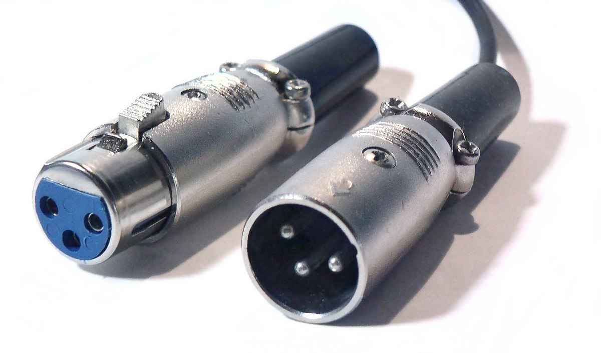
XLR Cable
Usually used for carrying signal from microphones to preamps, although it can be used for line level applications as well. XLR stands for ground (X); Left (L); Right (R).
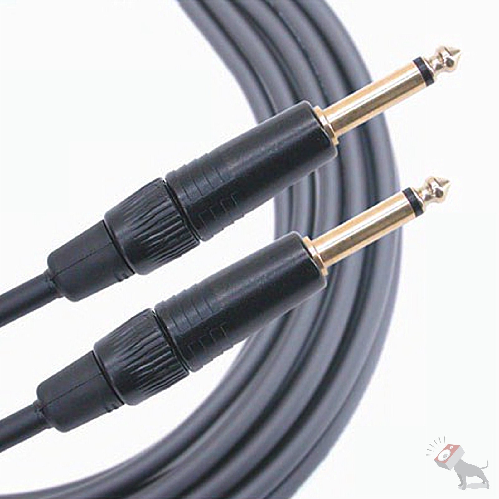
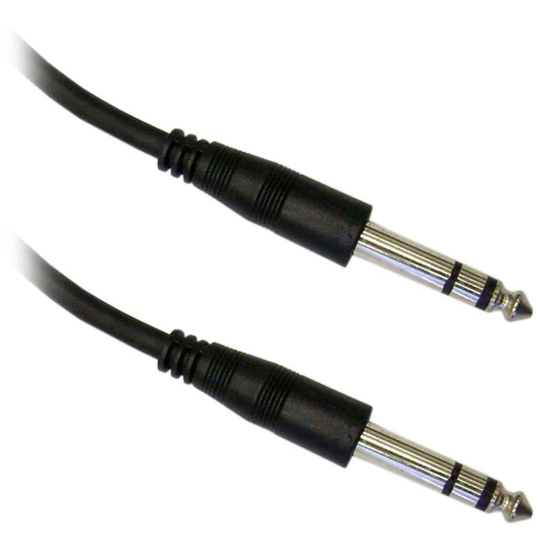
TRS Cable
Standing for tip (T); ring (R); sleeve (S). This balanced cable is most often used connecting balanced line level devices together.
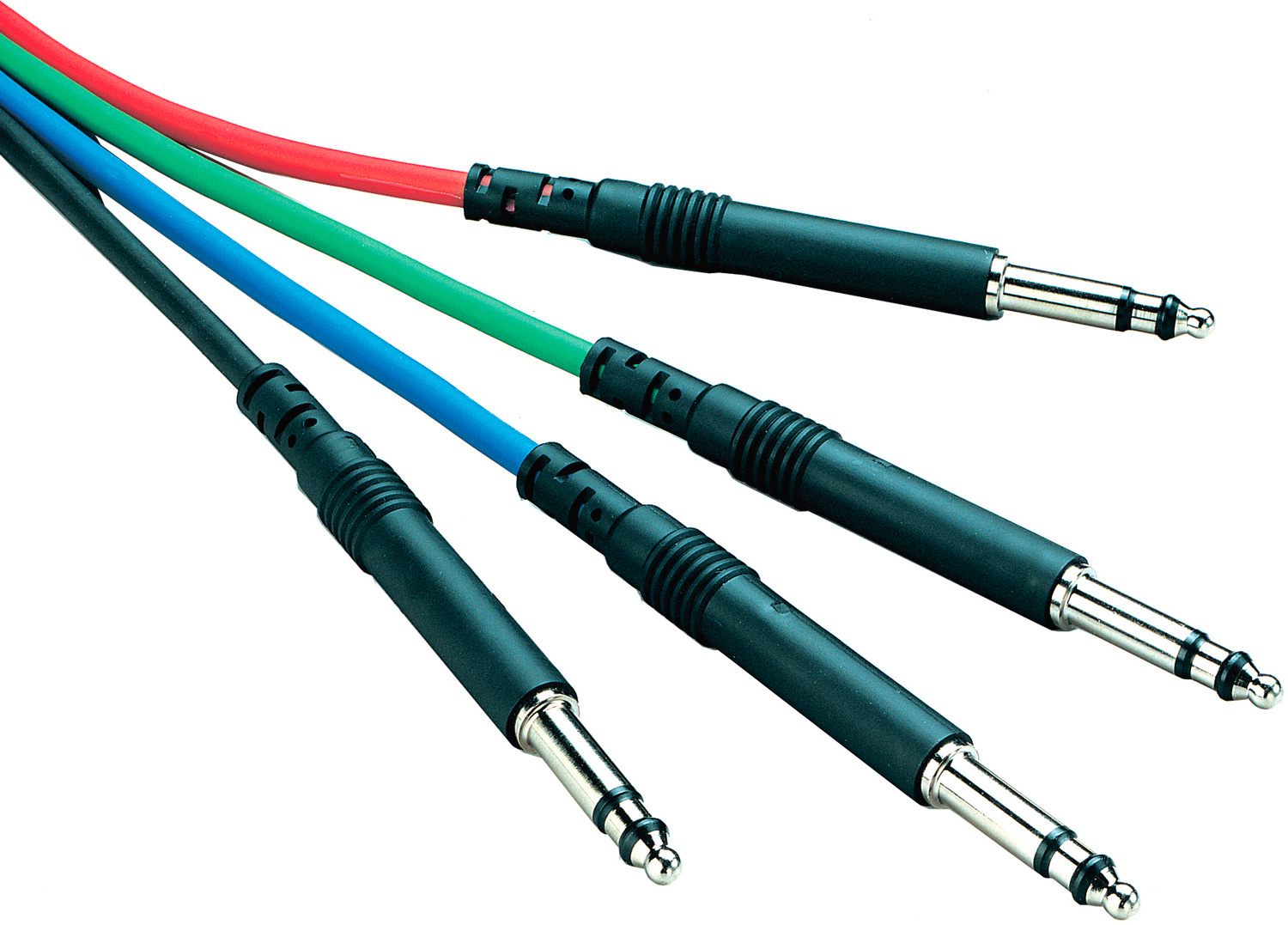
TT (Bantam) Cable
Standing for Tiny Telephone cable, these cables are almost exactly like TRS cables, except much smaller in size. These are used mostly in patch bays in recording studios. The name comes from its use in early telecommunications patch bays, hence the phrase, “I’ll patch you through.”
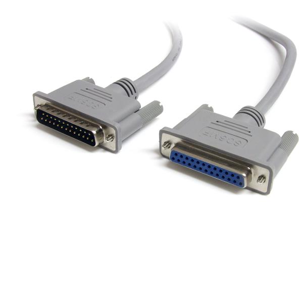
DB25 Cable (aka “DSUB”)
These are multichannel balanced cables designed for carrying multiple channels from one device to another with less cabling. These carry 8
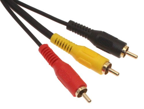
Unbalanced Cables
Using only two leads to carry signal, unbalanced cables are extremely common in stereo equipment and electric instruments. While balanced cables use a hot, cold, and ground, unbalanced cables use only a hot and ground. They can use the same cabling as long as the cold and ground are electronically tied together. The benefit of this design is that less circuitry is needed to process and carry signals. Less circuitry means costs stay lower for both unbalanced cabling and equipment designed for unbalanced signals. The drawbacks of this design is the possibility of radio frequency interference being introduced into the signal, as the ground path isn’t separated from the audio path.